Getting Started
Minimum setup
To start developing machine vision applications with the RPi Camera FMC, we recommend that you get setup with the minimum hardware and software requirements:
- An FPGA or MPSoC development board from our list of compatible boards.
- One RPi Camera FMC.
- At least one Raspberry Pi camera or compatible camera.
- Build and run one of our example designs.
Hardware setup
Attaching cameras
The four FFC camera connectors ( Amphenol ICC, FFC connector, SFW15R-1STE1LF ) are bottom contact connectors, meaning that the flex cable of the camera must be inserted with the contacts facing downwards. The images below illustrate the correct cable orientation when attaching cameras 1 and 2. The orientation is the same for cameras 0 and 3.
| Top view | Bottom view |
|---|---|
 |  |
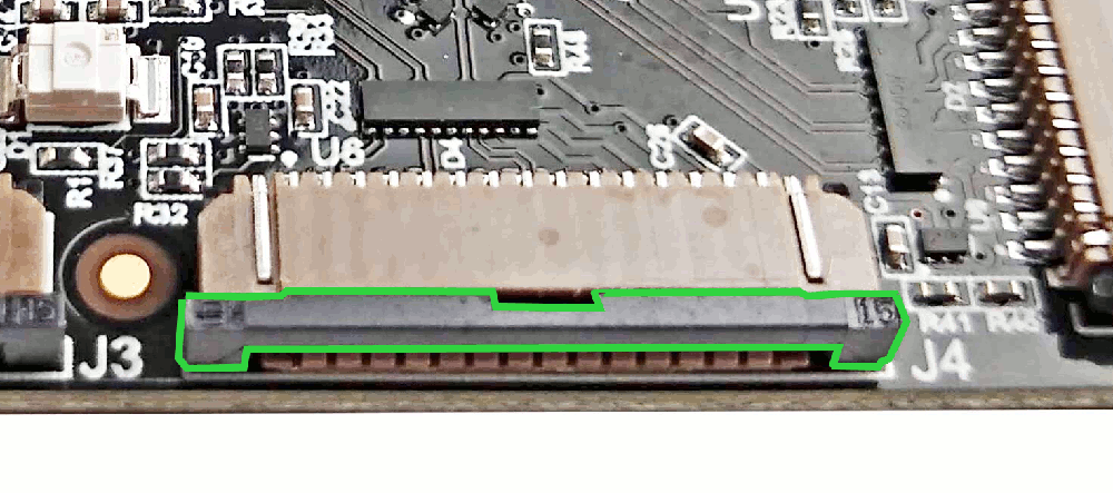
The camera connectors have a fastening (tightening) tab that prevents the flex cable from detaching once the fastener has been engaged. Before inserting the camera cable into the camera connector, you must first loosen the fastening tab by pulling on it from both sides of the connector. Note that the fastening tab does not come out of the connector, it should only be loosened, so be careful not to pull too hard. Once the fastening tab is loose, insert the flex cable with the correct orientation (as shown above), and then push the fastening tab back into the connector to lock the cable in place. The image below highlights the fastening tab in locked position, highlighted in green for clarity.
A useful video for understanding how to insert the camera can be seen below. However note that in this video they are inserting the camera into the Raspberry Pi - not the RPi Camera FMC.
When removing a camera, pull on the fastening tab to loosen it, then remove the flex cable.
We suggest that you connect the cameras to the mezzanine card before you plug the mezzanine card into the carrier board. The reason we suggest this is because the mezzanine is much easier to manipulate and the camera connectors are more visible when it is not attached to the carrier board.
Plugging into the carrier
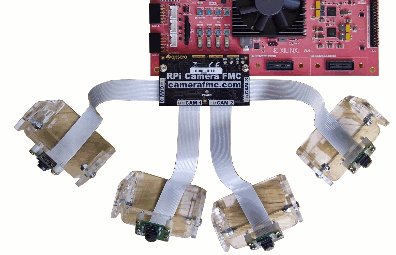
Connecting the mezzanine card into the carrier is fairly straightforward as the FMC connectors can only mate one way. The resulting setup should look like the image below:
To prevent the mezzanine card from detaching itself from the carrier (due to vibrations or camera positioning), we recommend using the included machine screws to fix the mezzanine card to the carrier board. The screws should be screwed into the mezzanine’s hex standoffs from the underside of the carrier board. Suitable screws are included with the RPi Camera FMC, however if they need to be replaced, the details on these screws can be found in the mechanical information section.
Software setup
In order to build our example designs, you will need to setup your PC with the AMD Xilinx development tools:
The Vivado and Vitis tools support most operating systems, whereas the PetaLinux tools can only be installed under Linux.
For the specific versions required, please refer to the release notes in the Git repository of the particular example design you wish to build.